Long ago, when we walked ten miles to school each day and made our own water, you needed lots of equipment to do any home microprocessor projects. That included things like an EPROM burner and a PCB etching tank. Now those were projects. The world has changed since we carved circuit boards out of stone and refined our own copper ore, so I thought I'd see what all this Arduino talk was all about.
|
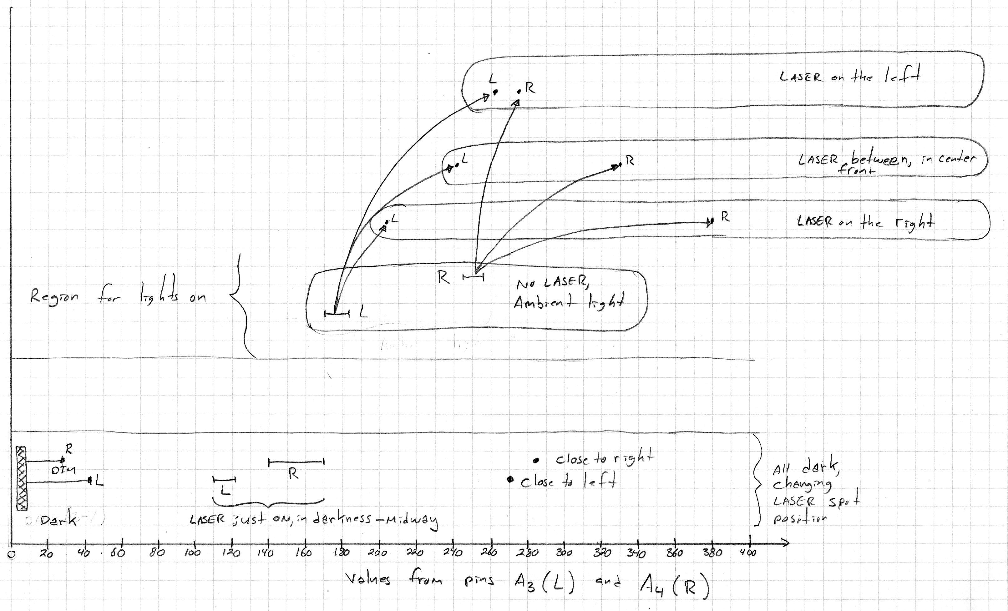
• From reset until 6 seconds it's calibrating, meaning it's recording the highest and lowest values picked up by any of its 4 sensors. Those are reference values it will use later.
• Then it chases the light. You will notice that the light has to be right in front of it. It can't see far away, and I'll go more into that problem later on. • At about 14 seconds it resets itself. That's a battery problem. • From 22 seconds on it's chasing smoke, or rather it's moved far enough out of its calibration range that it's chasing reflected light from the floor. |
|
|
|
|
|
|
|
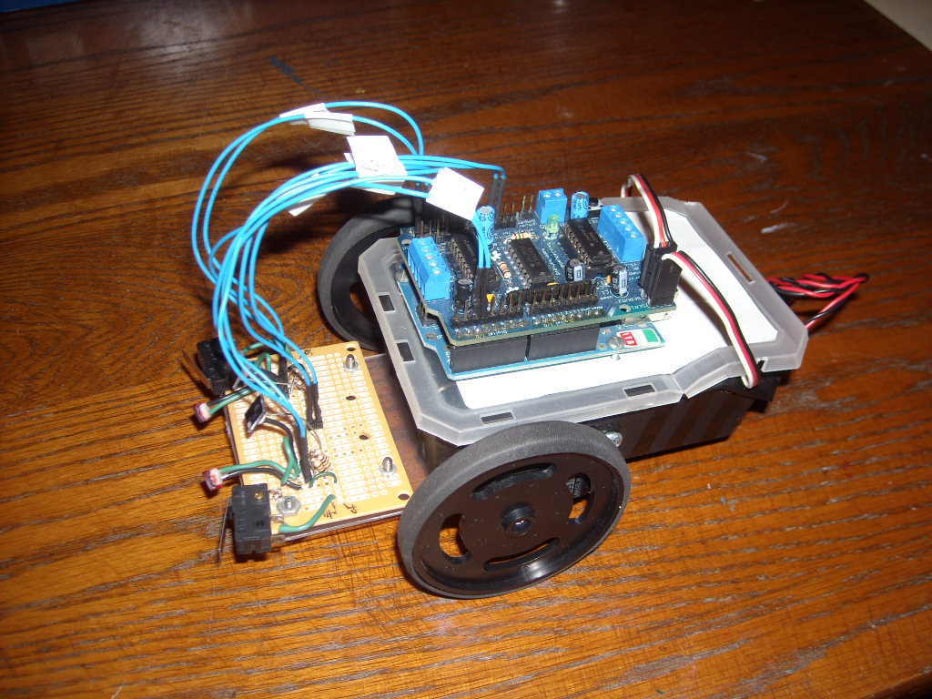
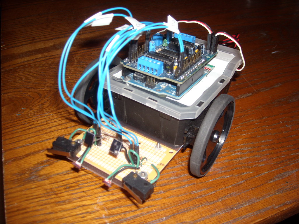
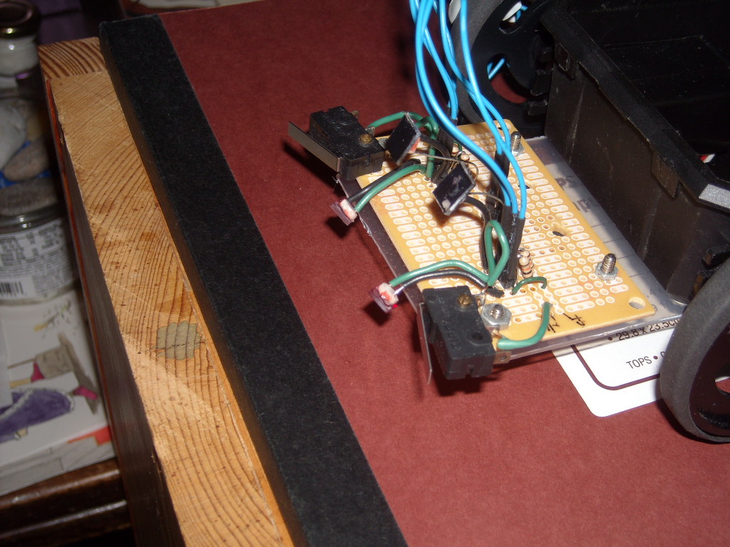
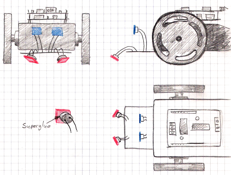
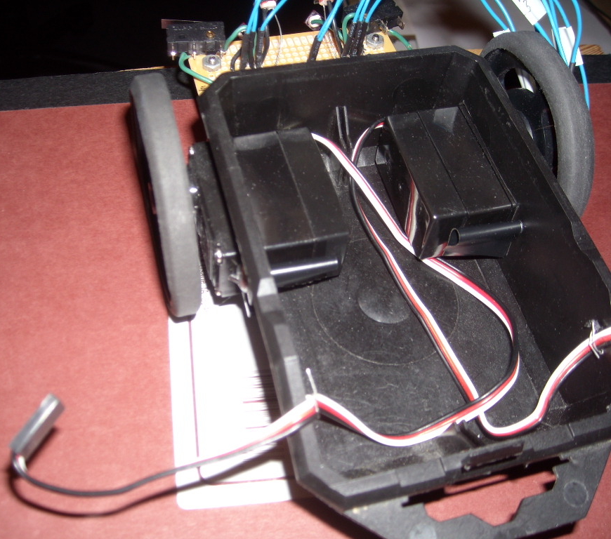
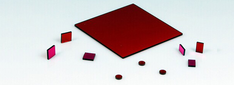
The 650nm bandpass filters are 6mm x 6mm square. I glued them onto the photoresistors. I don't have specifications on the blue filters because I just cut them from the front panel of an old DVD player.
The blue "eyes" filter out the red and respond otherwise to the ambient light (unless the ambient light is red). When the blue eyes detect brightness, the robot backs away. It's like the blue pill ... it's trying to go back to the way things were ... living in the dark unknown of artificial purpose. The red "eyes" are like the red pill ... and one could, if one were so inclined, make this robot follow the red light down into a rabbit hole. |
|
|
|
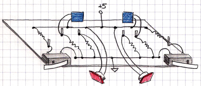
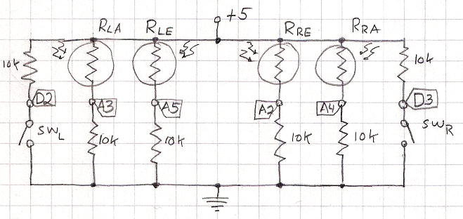
SWL : Left side bumper/switch SWR : Right side bumper/switch RLA : Resistor, Left Ambient RRA : Resistor, Right Ambient RLE : Resistor, Left Eye RRE : Resistor, Right Eye A2,A3,A4,A5 : Arduino analog pins 2 - 5 D2,D3 : Arduino digital pins 2 and 3 |
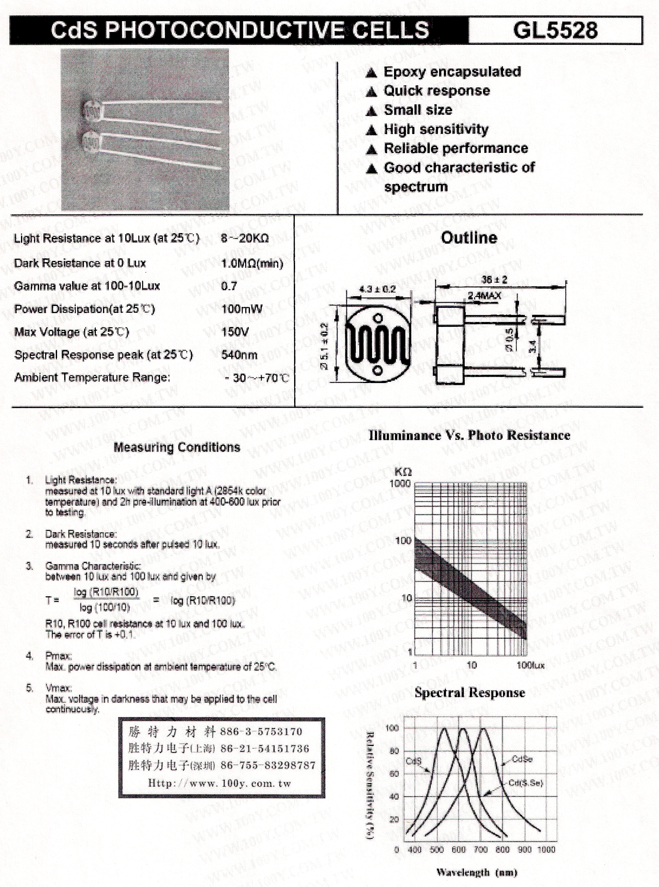
With a DVM I measured the photoresistor resistance in three conditions and got the following: 96KΩ with the room very dark. 700Ω with the room very bright. 1700Ω with the room normal, with the LASER light reflecting off a manila colored folder 1" away. From the circuit diagram, you can see it's a voltage divider with the photoresistors and a 10K fixed resistor. So that's 5v x 10K/(10K + RRxE) and that should provide a range of 0.47v to 4.27v: 5v x 10K/(10K + 96K) = 0.47 v 5v x 10K/(10K + 1.7K) = 4.27v So it's almost a factor of 10 from dark to bright. |
|
|
|
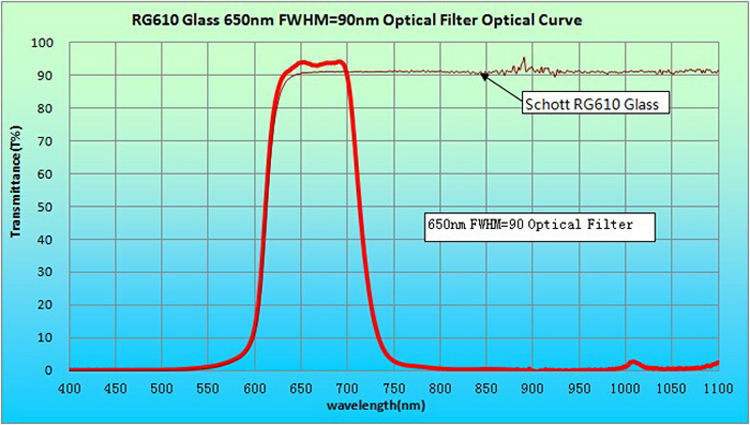
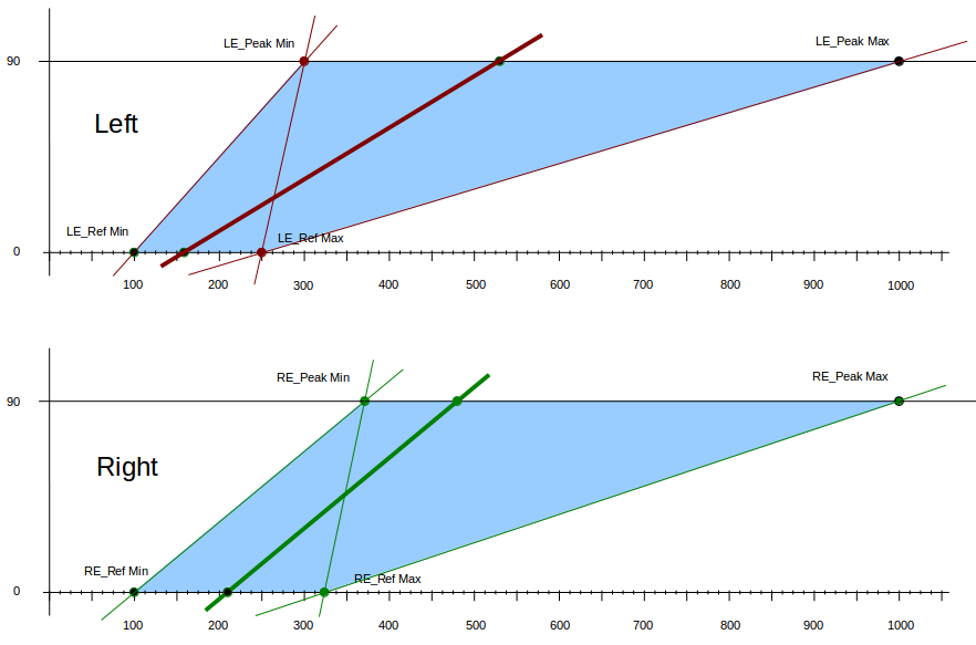
But that's not what I measure in the real system. Because I'm not going to try to do this in darkness, or to film in the dark, it's the difference between normal lighting and the normal lighting with the LASER light that matters. And from the plot above, that's only about 1.4x:
Right:Dark ―10x➝ Normal room light ―1.35x➝ LASER light close Left: Dark ―4x➝ Normal room light ―1.4x➝ LASER light close |
void loop()
{
  calibrating to find reference and peak values.
  ...
  calibration done
  ...
  // get the state of the outside world:
  RightEyeVal  = analogRead(RightEyePin);
  ...
     if (firsttimethrough == 1)
     {
       // Proportional is a y = mx +b kind of thing:
       mR = float(90/(float(RightEyePeak) - float(RE_Ref))) ;
       bR = mR*RE_Ref ;
     }


#ifdef USE_DERIVATIVE
    reloadRight = (RightEyeVal > RightEyeComputedVal) ? 1 : 0 ;
#else
    reloadRight = 0 ;
#endif
    RightEyeComputedVal = 0 ;


#ifdef USE_ROLLINGAVERAGE
    for (i=0 ; i < (ArrayLength-1); i++)
    {
      RightEyeComputedVal = RightEyeComputedVal + RightEyeArray[i] ;
      RightEyeArray[i]   = (reloadRight) ? RightEyeVal : RightEyeArray[i+1] ;
    }
    RightEyeArray[ArrayLength-1] = RightEyeVal ;
    RightEyeComputedVal = float ((RightEyeComputedVal + RightEyeVal)/ArrayLength) ;
#else
    RightEyeComputedVal = RightEyeVal;
#endif


      Left_Speed = int( (RightEyeComputedVal*mR) - bR) ;


#ifdef USE_BANG_BANG
      Rthresh = RE_Ref + 10 ;
      Lthresh = LE_Ref + 10 ;
      // Bang-bang control. Just go when the light is a wee bit above threshold.
      if ((RightEyeComputedVal > Rthresh)
           && (Left_EyeComputedVal > Lthresh)){ Left_Speed =  90 ; }
      else if (RightEyeComputedVal > Rthresh) { Left_Speed =  90 ; }
      else if (Left_EyeComputedVal > Lthresh) { Left_Speed = -90 ; }
      else                                    { Left_Speed =   0 ; }
#endif


      // Finally convert the values to L and R servo sense.
      // Lspeed above 90 is forward motion.
      Left_Speed = 90 + Left_Speed ;
      Left_Servo.write(Left_Speed) ;
...
}
const int LE_RefDesignMin  =  100;
const int LE_RefDesignMax  =  250;
const int LE_PeakDesignMin =  300;
const int LE_PeakDesignMax = 1000;

const int RE_RefDesignMin  =  100;
const int RE_RefDesignMax  =  320;
const int RE_PeakDesignMin =  370;
const int RE_PeakDesignMax = 1000;
| Bang-bang control. | |
| Decaying proportional control, also showing its back-away behaviour when encountering a bright light. | |
| Decaying Proportional and Poor-Man's Derivative control. |
|
|
| Arduino Duemilanove | A gift |
| Adafruit motor shield | (RD-Ada-02) Robotshop |
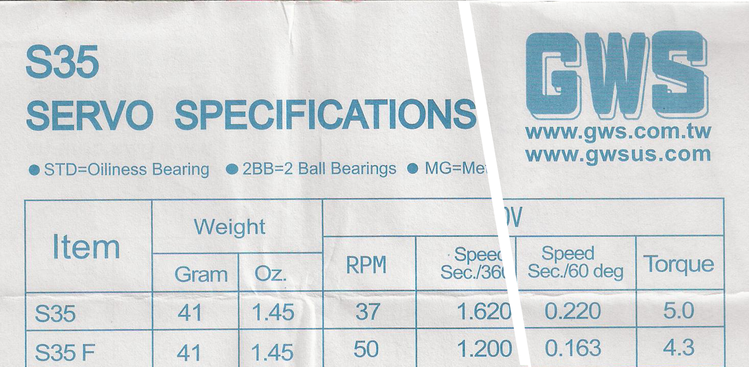
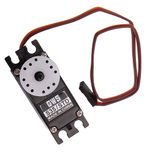
| 2x S35 GWS STD continuous rotation servo motor | (RB-GWS-23) Robotshop |
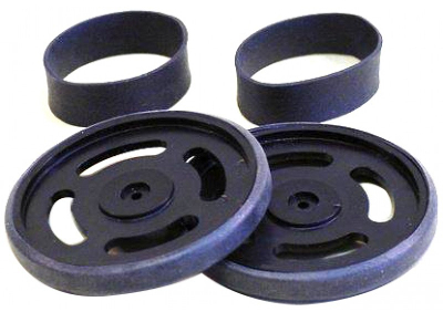
| Lynxmotion servo wheel 2.63" x 0.35" | (RB-Lyn-27) Robotshop |
| 4x Photocell GL5528 | Can't recall |
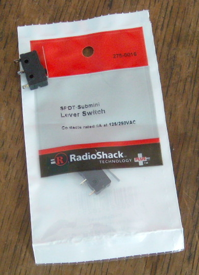
| 2x SPST switch | Radio Shack |
| 650nm filter | An OPTOLONG product, probably from Alibaba.com |
| blue light filter | front panel of an old DVD player |
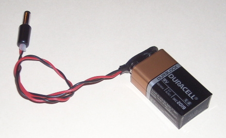
| battery connector | the box on the left on the floor |
| wires and resistors and perfboard and stuff | the other box on the floor, to the left of the first box |