A virtual DSP testbench
Other projects


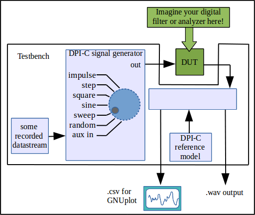
This small virtual testbench is for testing digital filter designs and other DSP functions.
The VirtualDSPtestbench contains a C-based signal generator whose behavior is selectable from the command line via 
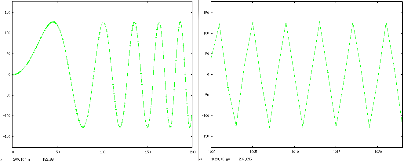
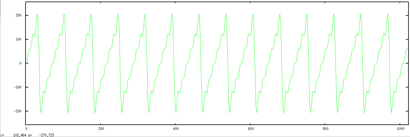
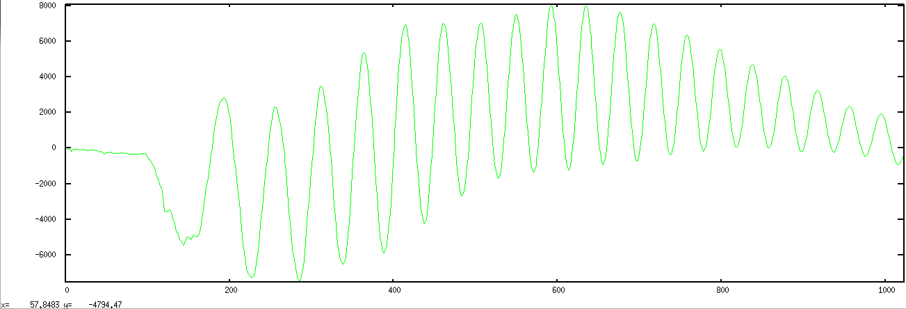
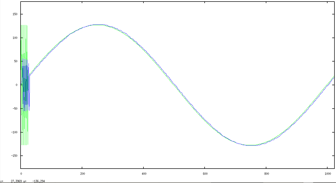
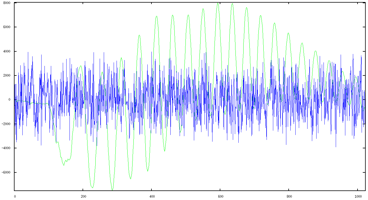
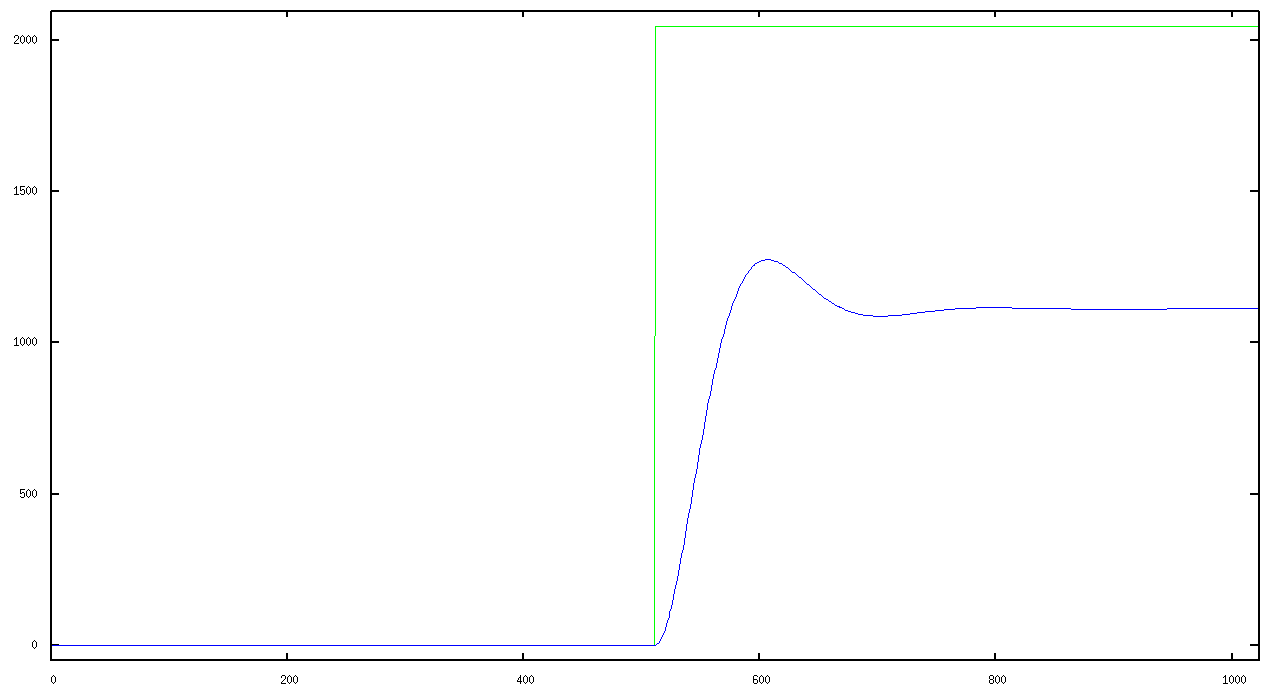
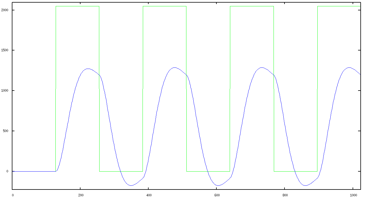
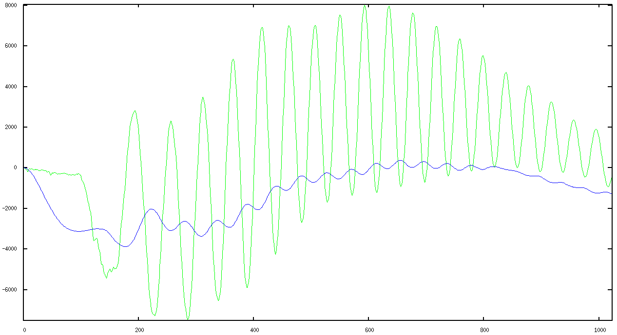
uvm_set_config_int. One of the functions includes a C-based file read, values from which are brought into a sequence as part of the testbench stimulus. So you can sing into EDA playground and filter it and write it back out to GNUplot or to a wav file. That's why I call it a "virtual" DSP testbench as it's in lieu of having the design in physical hardware. And like a physical bench with test equipment, it's designed so that one can drop in a DSP type DUT with minimal effort and and apply a standard array of stimuli to it: impulse, step, square, sinusoid, sinusoid sweep, random, and data streams of your own choosing.
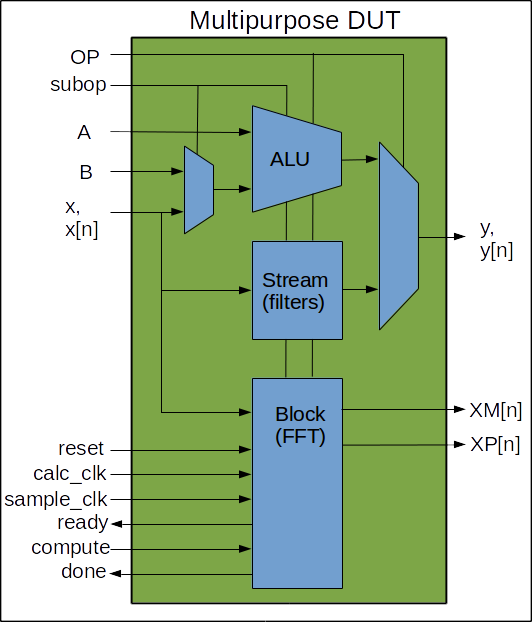
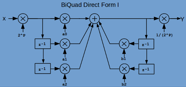
The input stimulus uses signed values, so the design uses signed values as well.

I'm going to need a lot of these multipliers ➞
So there is also a Perl script for turning
values like "-0.0014567" into Verilog
multiplier components suitable for use in
fixed-point signed arithmetic implementations.

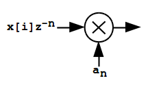
This is just in the beginning stage. The most recent testbench is on EDAplayground here:

The Setup
The multipurpose DUT
The testbench signal generator
The testbench output
The DUT
An example with a BiQuad LPF
Further work


The setup

The diagram below shows what I'd like to mimic: a signal generator, mic, oscilloscope, spectrum analyzer, and an amp & speaker. This provides me the ability to drop in digital filter designs, subject them to standard stimulus, and see if they are worth committing to an FPGA build. So this is less of a full-fledged UVM verification environment than it is a proof-of-concept testbench.


The multipurpose DUT

There are three basic types of devices I'll be testing, and in the diagram below I've indicated them by the transfer operation type: ALU, Stream, and Block. The "OP" selects one of those OPerations. Each block may take parameters given as subop.

  • ALU:
    For ALU type DUTs, the testbench provides stimulus as a sequence of two integers, or one integer and an stream of data, and output is on y, y[n]. The stream comes from a signal generator which is implemented in a C program integrated via the DPI. Testing of ALU type components is done via the tests:
    From the base test OP_ALUbase_test,
    +UVM_TESTNAME=OP_ADD_test
    +UVM_TESTNAME=OP_MULT_test
    +UVM_TESTNAME=OP_INV_test
    +UVM_TESTNAME=OP_SQRT_test


  • Stream:
    For filter type DUTs, the testbench provides stimulus as stream of data on x[n] and the output is on y[n]. The stream comes from a signal generator which is implemented in a C program integrated via the DPI. Testing of ALU type components is done via the tests:
    From the base test OP_ContinuousSampleBase_test
    +UVM_TESTNAME=OP_LPFfir1_test
    +UVM_TESTNAME=OP_BiQuadLPF_1_test


  • Block:
    For analysis components requiring block transfers, like an FFT, the testbench provides stimulus as stream of data on x[n], which is buffered, computations can then be performed, and the output is on XM[n] (Magnitude) and XP[n] (Phase). The stream comes from a signal generator which is implemented in a C program integrated via the DPI. Testing of Block type components is done via the tests:
    From the base test OP_BlockTXFRBase_test
    +UVM_TESTNAME=OP_FFT_0DC_HANN_padZ_rdx2_nrml_test


    The testbench signal generator

    The testbench consists of stimulus from either a simple sequence item of two integers, or a function generator which is implemented in a C program integrated via the DPI. The set of integers is for testing ALU type components via the tests: The signal generator provides a single stream of input values to the DUT. This is all brand new, so the only DUTs are a simple low-pass filter implemented as an FIR and a LPF BiQuad. The testname names the DUT, the stimulus is named by the SIGNAL added on the command line as shown:
      +UVM_TESTNAME=OP_LPFfir1_test (the default is a sine wave).
      +UVM_TESTNAME=OP_LPFfir1_test +uvm_set_config_int=*,SIGNAL,0     (DC)
                                    +uvm_set_config_int=*,SIGNAL,1     (IMPULSE)
                                    +uvm_set_config_int=*,SIGNAL,2     (STEP)
                                    +uvm_set_config_int=*,SIGNAL,3     (SQUARE)
                                    +uvm_set_config_int=*,SIGNAL,4     (SINE)
                                    +uvm_set_config_int=*,SIGNAL,5     (SWEEP)
                                    +uvm_set_config_int=*,SIGNAL,6     (KSP135N246)
                                    +uvm_set_config_int=*,SIGNAL,7     (FILE_READ)
                                    +uvm_set_config_int=*,SIGNAL,8     (RANDOM)
                                    +uvm_set_config_int=*,SIGNAL,9     (MINSAMPLES, 4 samples/cycle)
                                    +uvm_set_config_int=*,SIGNAL,10    (MAXSAMPLES, 1 (ish) sine wave per 1024 samples)
                                    +uvm_set_config_int=*,SIGNAL,11    (MIN_MAX, burst of '9' then '10')
    
    While there is nothing like reading the source "signal_generator.c" for details of what these 12 functions do, here is an explanation of each function. Legal values for SIGNAL are defined in OP_TBdefines_pkg.svh:
    package TBdefs_pkg ;
    
    `define SEQUENCE_LENGTH 1024
    
    // Here's something odd. I've got the sequence looking at the SIG_type to 
    // determine if it should call a single input function or a randomized two-input
    // transaction. It does that with a compare of (signal < TWOINPUT). So, all
    // enum functions for single signal sequences for x[n] should be put to the
    // left of "TWOINPUT". 
    // The inputs up to but not including TWOINPUT come from the signal_generator.c
    // function and are intended to be used as a single sampled data stream of +/- integers.
    // The TWOINPUT is just a switch to use randomized transactions for computational
    // units that require a pair of values. Like an ALU might want.
    typedef enum bit[5:0] { DC, IMPULSE, STEP, SQUARE, 
                            SINE, SWEEP, KSP135N246, FILE_READ, RANDOM, MINSAMPLES, MAXSAMPLES, MIN_MAX, 
                            TWOINPUT } SIG_type ;
    endpackage
    
    The sequence will make SEQUENCE_LENGTH number of calls the signal generator like so:
    in_tx.x_in = signal_generator(signal, amplitude, offset, period, phase, samplenumber, sg_maxval, sg_minval) ;

  • SIGNAL,0 DC
       Return the value of amplitude.

  • SIGNAL,1 IMPULSE
       Return the value of 0 except for a single value of amplitude in the middle of SEQUENCE_LENGTH.

  • SIGNAL,2 STEP
       Return the value of 0 for the first half of SEQUENCE_LENGTH then apply the value of amplitude for the remainder.

  • SIGNAL,3 SQUARE
       Return the value of 0 + offset and amplitude+offset alternately for 1/8 of SEQUENCE_LENGTH.

  • SIGNAL,4 SINE
       Return the value of offset+amplitude * sin (2πfARB*samplenumber + phase). See note below on fARB.


  • SIGNAL,5 SWEEP
       Return the value of
    offset+amplitude * sin (2πfmint + phase) to
    offset+amplitude * sin (2πfmaxt + phase)
    as samplenumber goes from 0 to SEQUENCE_LENGTH. See note below on fmin and fmax.
    The sweep is done with the following expression:
    return (int) amplitude * sin ((double)samplenumber * (double)(sweepmult++)/1304.0) ;
    which could use some explanation. At present the 1304 is tied to the SEQUENCE_LENGTH and 2 x the Nyquist frequency. This is a linear sweep where the argument to the sine function increases by a factor, M, of the sweepcount with each sample.
    Now I want at least 4 samples per cycle at the end of the sweep. That means the difference between the last two argument to the sine function must be less than 90o, or 1.57 radians. From the expression above, those samples are:
    samplenumber * sweepmult * M = 1023 * 1023 * M, and
    samplenumber * sweepmult * M = 1024 * 1024 * M.
    For the difference to be less than 1.57:
    2048 * M < 1.57 , M > 1304
    Here's a screenshot of the sweep:

    Here's a screenshot of the first 200 and the last 24 samples of the sweep above:


  • SIGNAL,6 KSP135N246
       Return the value of offset+
    (amplitude/1) * sin (1*2πfARB*samplenumber + phase) +
    (amplitude/3) * sin (3*2πfARB*samplenumber + phase) +
    (amplitude/5) * sin (5*2πfARB*samplenumber + phase) +
    (-amplitude/2) * sin (2*2πfARB*samplenumber + phase) +
    (-amplitude/4) * sin (4*2πfARB*samplenumber + phase) +
    (-amplitude/6) * sin (6*2πfARB*samplenumber + phase).
    See note below on fARB.


  • SIGNAL,7 FILE_READ
       The file audiovalues.txt contains one integer value per line, so it's an array audiofile[line number].
       Return the value of audiofile[samplenumber]. That file contains whatever I last felt like recording into the microphone and converting and uploading as that file. I'll make that selectable from the command line soon.


  • SIGNAL,8 RANDOM
       Return a random value between +/- amplitude.

  • SIGNAL,9 MINSAMPLES, 4 samples/cycle
       Return the value of
    offset+amplitude * sin (2πfmaxt + phase). See note below on fmax.

  • SIGNAL,10 MAXSAMPLES, 1 (ish) sine wave per 1024 samples
       Return the value of
    offset+amplitude * sin (2πfmint + phase). See note below on fmin.

  • SIGNAL,11 MIN_MAX, burst of '9' then '10'.
       Return the value of
    offset+amplitude * sin (2πfmaxt + phase) for 24 samples then return
    offset+amplitude * sin (2πfmint + phase) to the end of SEQUENCE_LENGTH.
    Here is an image of the MIN_MAX sequence showing both fmax and fmin sine waves in the current SEQUENCE_LENGTH of 1024 samples. The green is the input, the blue the output. The noddy LPF has some amplitude issues with the higher frequency but passes nicely with the lower.


    NOTES:
    Capacitors and inductors are reality aware in ways that digital filters will never understand. It's all just a bunch of samples. Nonetheless, the ARBitrary sample rate I've chosen is 44.1kHz, because some of the stimulus was in reality sampled at that frequency. The audio files are beatbox sounds and low and high E strings on a guitar. Because I know the frequency and spectra of such signals, and because I want to see the output displayed, I've chosen an arbitrary frequency that provides a fair number of cycles to be visible in the plot. So there is no "frequency", there are only settings on my virtual oscilloscope. Like is says above, this is not an analysis testbench but rather one where I can subject designs to standard stimulus, and see if they are worth committing to an FPGA build. I can get a lot of that information just by looking at a graph.
  • fARB is just the value to provide about 25 cycles in a SEQUENCE_LENGTH of 1024.
  • fmax is just the value to provide 4 samples / cycles. That's twice the Nyquist rate and again, it's just so I can see a few samples per cycle and not just know that with enough signal analysis I could detect the highest frequency sine wave.
  • fmin is just the value to provide about 1 cycle in a SEQUENCE_LENGTH of 1024.

    Note that the combination of wanting to see at minimum 4 samples per cycle and one cycle per 1024 samples gives a total range for the SWEEP function of only a factor of 250. If I wanted to see a frequency range of 104 I'd need only to increase the SEQUENCE_LENGTH to 64K.


    The testbench output

    At present, I just copy the output from the log file and give it to a script which generates plots via GNUplot.


    The DUT

  • The ALU OP takes one subop for changing the input source.
  • The Stream OP takes zero subops at the present time.
  • The Block OP takes as many subops as the DUT needs and in an order determined by the tester. Remember, this is meant to be like a physical test setup, where you can turn a dial and push a button and flip a DIP switch and have different stimulus and different DUT behavior. Therefore there will be a new uvm_test for each Block operation. Extend from the base test OP_BlockTXFRBase_test which will always do an initialization, a block write, call some computation task or set of tasks with dothese(), and finish with a block read:
      task run_phase(uvm_phase phase);
        phase.raise_objection(this);
    
        begin
          InitBlock_sequence in_seq;
          in_seq = InitBlock_sequence::type_id::create("in_seq");
          in_seq.start(env.opagent.opsequencer);
        end
    
        repeat (sequence_length) begin
          WriteBlock_sequence in_seq;
          in_seq = WriteBlock_sequence::type_id::create("in_seq");
          in_seq.start(env.opagent.opsequencer);
        end
    
        dothese() ; // override this in the extended test
    
        repeat (sequence_length) begin
          ReadBlock_sequence in_seq ;
          in_seq = ReadBlock_sequence::type_id::create("in_seq");
          in_seq.start(env.opagent.opsequencer);
        end
    
        phase.drop_objection(this);
      endtask
    
    Individual test provide an implementation of dothese() in the extended test. For example, here's what the test OP_FFT_0DC_HANN_padZ_rdx2_nrml_test does for an implementation of dothese(). Each sequence in the task sets subop to a new value, then asserts compute, and awaits done:
      task dothese() ;
        remove_DC_offset_sequence  in_seq ;
        ...
        apply_HANN_window_sequence in_seq ;
        ...
        padZeros_sequence          in_seq ;
        ...
        doFFTradx2_sequence        in_seq ;
        ...
        normalizeFFT_sequence      in_seq ;
        ...                                                      
      endtask
    
    Here is a block diagram of the insides of the Block of the Multipurpose DUT. Like everything else on this page, the diagrams below are only a first draft, just meant to convey the idea. If the OPeration is a block type, then after writing the block, set a subop value, assert compute until done is asserted, set the next subop value, assert compute until done is asserted, ..., continue until you want to read out the results. The only implementation at this early stage is a collection of dummy activity meant to support testbench development. I mean, we all build the testbench first, don't we?


    An example with a BiQuad LPF

    The DUT has a second-order LPF implemented as a BiQuad IIR. Here is a diagram of that filter:


    This implements

    y[n] = (2P * (a0*x[n] + a1*x[n-1] + a2*x[n-2] + (-b1)*y[n-1] + (-b2)*y[n-2]) /(2P))

    The 2P and 1/(2P) are prescaler and postscalars. The coefficients for this biquad are very small, a0 for example is 0.00019897136836160073. Multiplication of any number less than 5026 (1/0.00019897136836160073) will amount to Zero in this fixed-point implementation. Prescaling by a factor of 216 keep small numbers from geting truncated to zero. The postscalar makes a final readjustment.

    The input signal is what I call the "goldfish bubble" (and you can hear it here GoldfishBubble.wav). It consists primarily of two sinewaves, one at about 21Hz and another at about 880Hz. This particular filter is a second order lowpass with an Fcutoff of 200Hz with an Fsample of 44,100.

    I got the coefficients from the wonderful EarLevel website here: http://www.earlevel.com/main/.

    I'm going to need a lot of multipliers, so I wrote a Perl script to generate them. That script is here: base10to32bitandQscale.pl. It provides the coefficients in 16-bit 2's complement form after multiplying the coefficient up by 2Q, where Q is whatever it needs to be to make the resulting scaled coefficient greater than or equal to 1023. Again, this is a fixed point implementation, so the fractional coefficients are represented as some 2's complement integer and an integer power of 2, post-multiplication divider. I chose >= 1024 because the worst case truncation of the lower bits of the coefficient is still less than 0.1% error.
    % ./base10to32bitandQscale.pl a0=0.00019897136836160073
    //-------------------------------------------------------------
     Mult16bitByConstFixed a0_inst ( 	// a0 = 0.00019897136836160073
       .Q     ('d23),                	//
       .coeff (16'b0000011010000101),	// (a0base2) x 2^23
       .B     (BBBBBBBa0),           	//
       .y     (yyyyyyya0)            	// y = coeff*B >>> Q
     ) ;
    
    ./base10to32bitandQscale.pl a1=-0.085198971368361
    //-------------------------------------------------------------
     Mult16bitByConstFixed a1_inst ( 	// a1 = -0.085198971368361
       .Q     ('d14),                	//
       .coeff (16'b1111101010001101),	// (a1base2) x 2^14
       .B     (BBBBBBBa1),           	//
       .y     (yyyyyyya1)            	// y = coeff*B >>> Q
     ) ;
    

    Here are some screenshots of the filter in use, green is the input and blue is the output. The testname is OP_BiQuadLPF_1_test and here is the oputput for different "settings" of the signal generator:
    This was the first test of the filter ... and shows what happens when one fails to get the sign of the coefficients in the feedback path right:

    Much better now. Here is the step response:
    +UVM_TESTNAME=OP_BiQuadLPF_1_test +uvm_set_config_int=*,SIGNAL,2

    Response to an input square wave:
    +UVM_TESTNAME=OP_BiQuadLPF_1_test +uvm_set_config_int=*,SIGNAL,3

    Response to the GoldfishBubble audio file:
    +UVM_TESTNAME=OP_BiQuadLPF_1_test +uvm_set_config_int=*,SIGNAL,7


    Further work

    If you have code improvements or corrections or things you'd like to see or share, please let me know. Just go to the "Other Projects" link and navigate to "Contact".