Audio Delay Perception Test
Other projects


For this little project I made a small device for a psychoacoustic test of human delay perception. I'm building a system which converts vocal percussion sounds, like /ta/, /da/, & /tee/, into MIDI data in real-time. So I need to know what my "real-time" timing budget is. There is a lot of research and much more of just people talking about what delay one can tolearate before it no lnoger feels like "real time".
This is actually a pretty easy thing to test. And I'll test it in a real system such as one I have a home, since the hardware I am developing will run in that environment.


The problem to be solved

The cartoon version:
I'm building a system which converts vocal percussion sounds, like /ta/, /da/, & /tee/, into MIDI data in real-time. The cartoon version looks like this, and the delay I cannot violate is treal-time-minimum.

The time treal-time-minimum comprises several other time delays. I don't know what they are but I do know that
  • The perception of simultaneity has to be determined empirically, and
  • the only time I really have any control over and can use is encapsulated in tc
  • whatever the audio equipment delays are, they are nothing compared to moving a foot closer or farther from the monitor speaker since that change is almost 10msec.
I already know that I need circuitry for the blue box labeled "Threshold Detection" and "MIDI signal initiation and transmission", so I built a small Arduio based delay box. This is NOT an audio delay. It's a delay from detection of any above threshold input to sending out a MIDI note ... determined by whatever patch is selected on the keyboard.


The hardware


The actual system:
Here is the actual system I'm using, one just like everyone has at home. Except for that small black box on the stool. I run the mic and drum machine to a mixer and the aux out to the Marshall and line out to the box.

The box responds to any sound level over threshold and sends a signal to initiate a MIDI note-on transmission. There is a block-out period in the analog circuit of 100msec to keep signals from retriggering the MIDI note-on. Mostly this is a practical matter, but 100msec repetition of any sound is 10Hz, and that sounds like a tone. And 10 phonemes per second is about the rate of normal speech. So for this test a block-out period of 100msec seems reasonable.

The delay block and box:
Just gratuitous photos of the outside and insides of the box. The analog board is underneath the digital board.

The Arduio code and delay box schematics:
The note on period is 200msec.
The note off is followed by 100msec of delay.
So the maximum rate of input sounds is 3 per second.
/*
  Much of this code is lifted directly from:
  MIDI note player :: 
      http://www.arduino.cc/en/Tutorial/Midi :: 
        by Tom Igoe
  LiquidCrystal Library - Hello World ::
      http://www.arduino.cc/en/Tutorial/LiquidCrystal ::
        by David A. Mellis
        by Limor Fried (http://www.ladyada.net)
        by Tom Igoe

  The circuit:
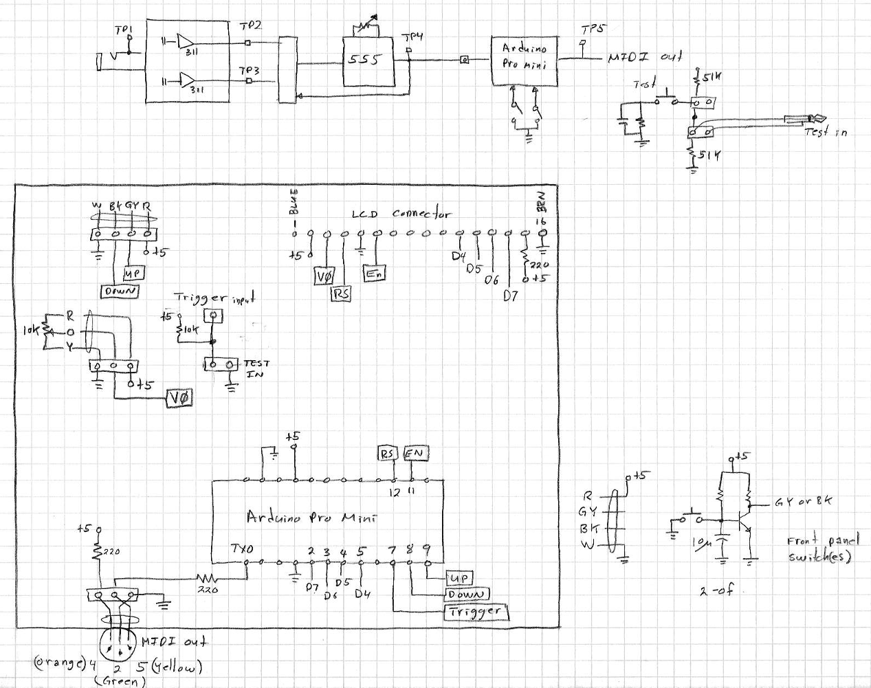
  * digital in 1 connected to MIDI jack pin 5
  * MIDI jack pin 2 connected to ground
  * MIDI jack pin 4 connected to +5V through 220-ohm resistor
  The circuit:
  * LCD RS pin to digital pin 12
  * LCD Enable pin to digital pin 11
  * LCD D4 pin to digital pin 5
  * LCD D5 pin to digital pin 4
  * LCD D6 pin to digital pin 3
  * LCD D7 pin to digital pin 2
  * LCD R/W pin to ground
  * LCD VSS pin to ground
  * LCD VCC pin to 5V
  * 10K resistor: +5V and ground, wiper to LCD VO pin (pin 3)

 This example code is in the public domain.  */

#include 

LiquidCrystal lcd(12, 11, 5, 4, 3, 2);
const int count_down = 9; // panel toggle switch moved left
const int count_up   = 8; // panel toggle switch moved right
const int trigger    = 7; // analog board's 555 output pulse.
int count_up_Val     = 0;
int count_down_Val   = 0;
int trigger_Val      = 0;
int count = 1 ;
int delay_val = 0 ;

void setup() 
{
  pinMode(count_up,   INPUT);
  pinMode(count_down, INPUT);
  pinMode(trigger,    INPUT);
  lcd.begin(16, 2);
  lcd.setCursor(0, 0);
  lcd.print("starting up ...");
  Serial.begin(31250);        //  Set MIDI baud rate:
  delay(1000) ;
  lcd.clear();
  delay(500) ;
  lcd.setCursor(0, 1);
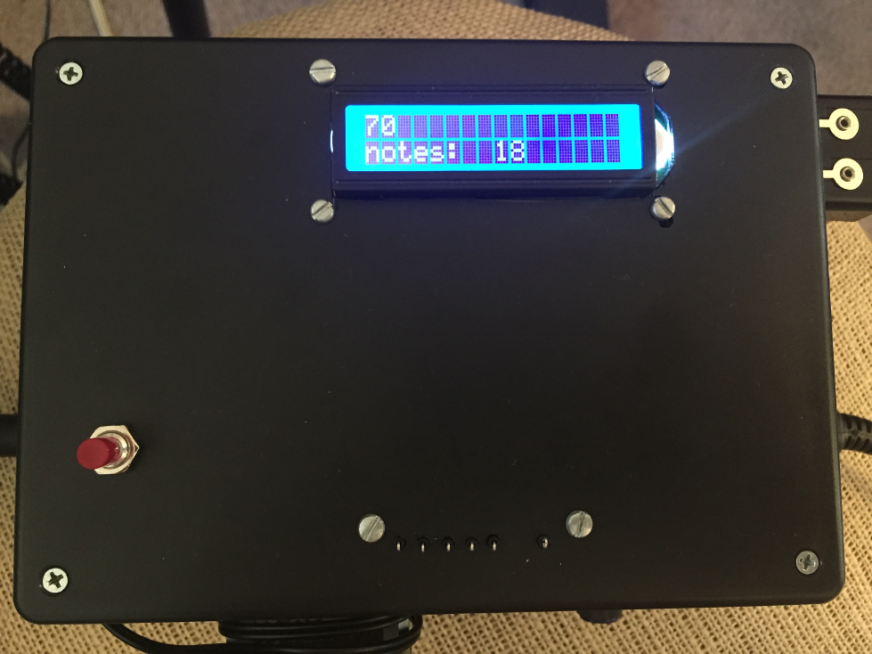
  lcd.print("notes:");
}

void loop() 
{
  trigger_Val    = digitalRead(trigger);
     
  if (trigger_Val == HIGH)     
  {
    delay(delay_val) ;
    //Note on channel 1 (0x90), note value, mid velocity (0x45):
    noteOn(0x90, 0x3C, 0x45);
    delay(200);
    // same note, silent velocity (0x00):
    noteOn(0x90, 0x3C, 0x00);
    delay(100);
    lcd.setCursor(8, 1);
    lcd.print(count);
    count++ ;
  }
  else 
  { 
    count_up_Val   = digitalRead(count_up);
    count_down_Val = digitalRead(count_down);
    
    if (( count_up_Val == HIGH) || (count_down_Val == HIGH))
    {
      if      (count_up_Val == HIGH)
      {
        delay(200); delay_val++;
      }
      else if (count_down_Val == HIGH)  
      {
        delay(200); delay_val-- ; 
        if (delay_val < 0) delay_val = 0 ;
      }
      lcd.setCursor(0,  0);
      lcd.print("     ");
      lcd.setCursor(0,  0);
      lcd.print(delay_val);
    }
  }
}

//  plays a MIDI note.  Does not check to see that
//  cmd is > than 127, or data values < 127:
void noteOn(int cmd, int pitch, int velocity) 
{
  Serial.write(cmd); Serial.write(pitch); Serial.write(velocity);
}
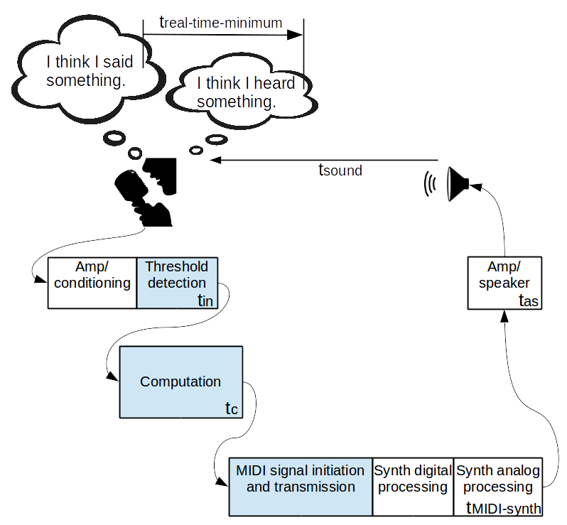
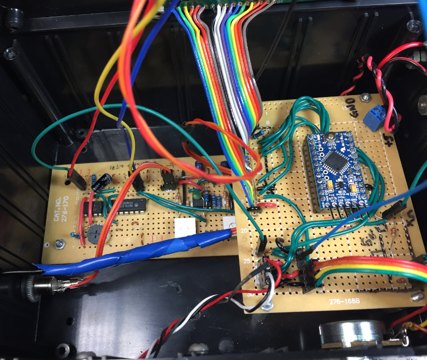
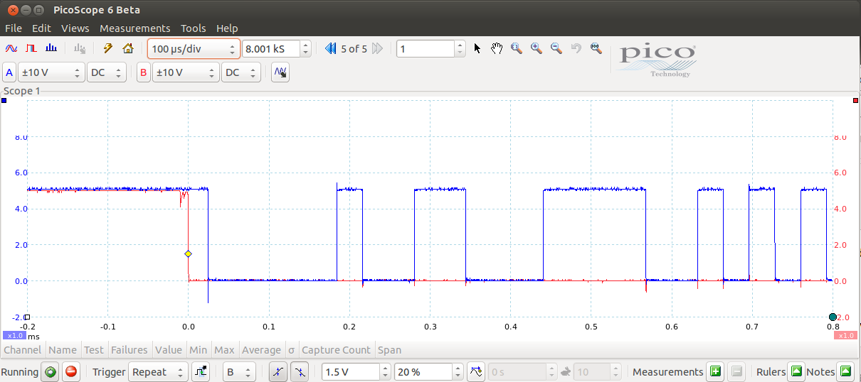
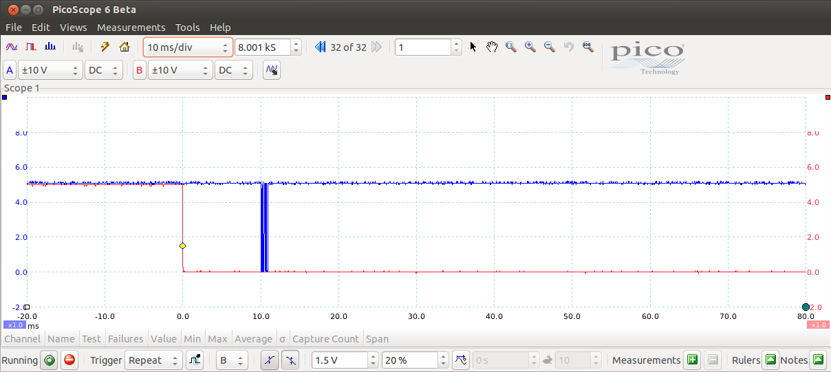
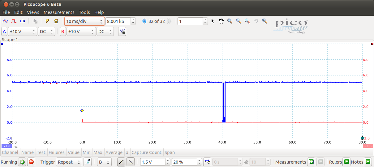
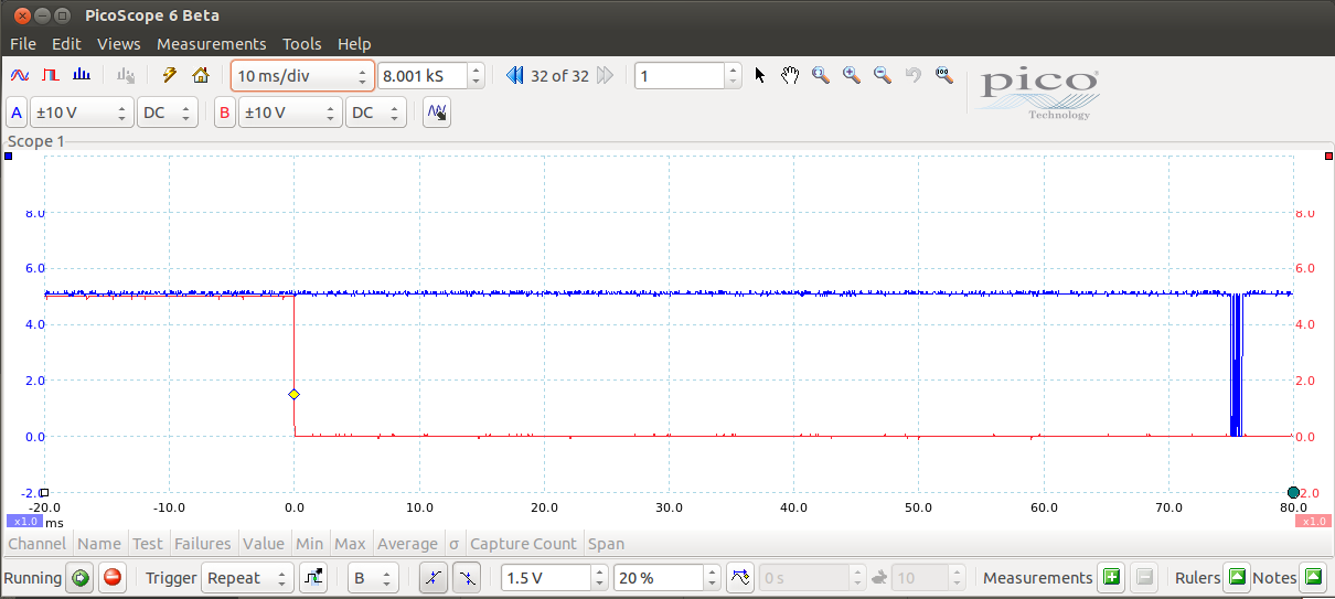
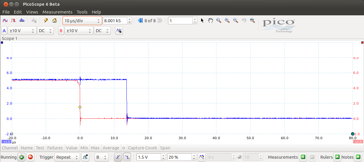
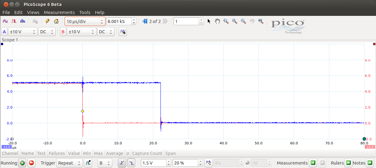
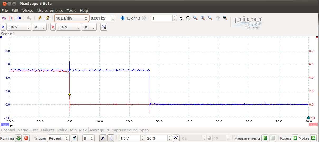
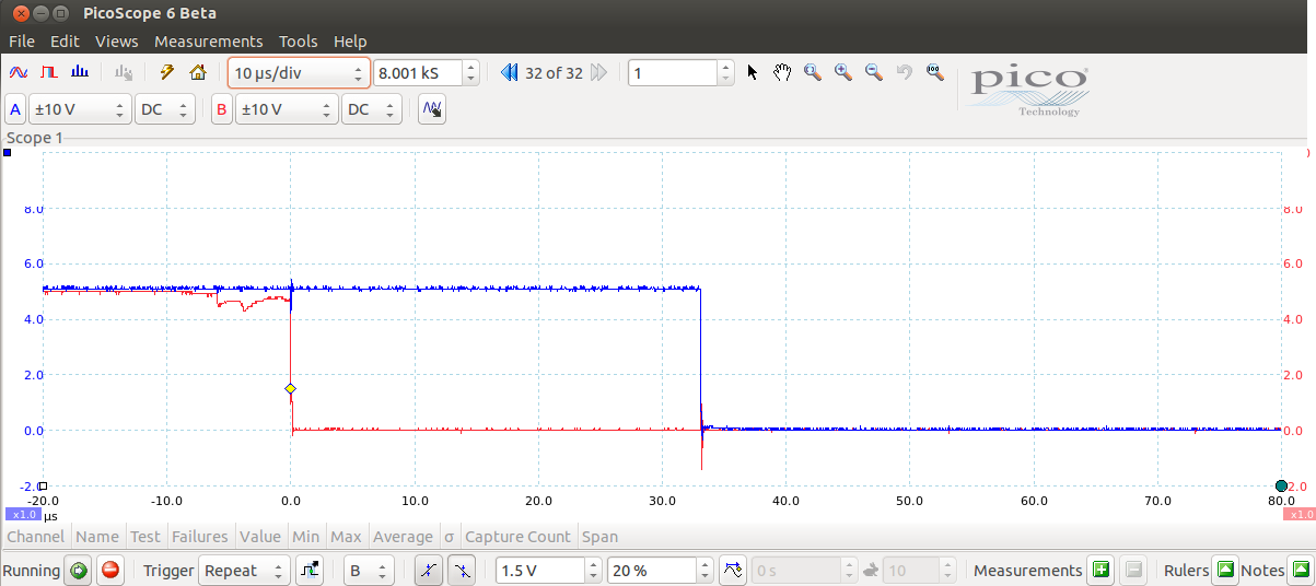
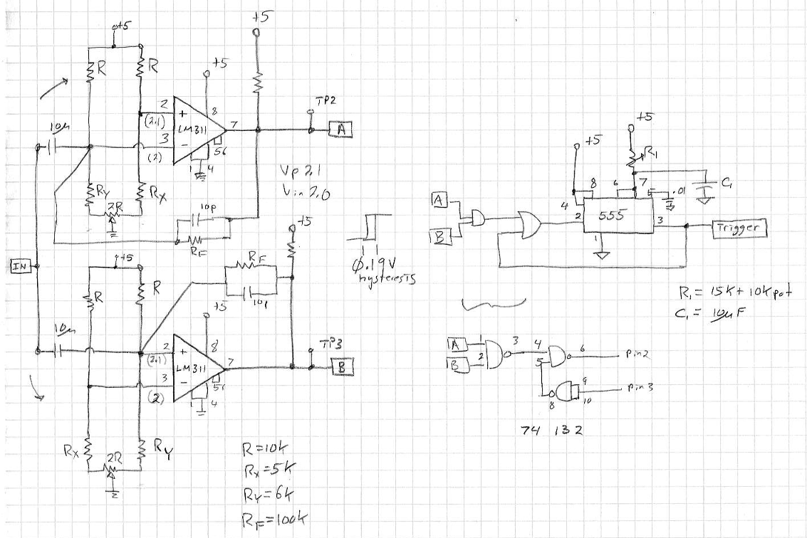
If you look at the schematic you will see two LM311 threshold comparators. That's because the direction (+/-) of the leading edge of the signal depends on which way the microphone is facing. That circuit takes whichever output transistions first and passes it to the 555 timer.


The delay box output

More gratuitous screenshots, this time from the PicoScope showing the burst of MIDI
serial data w.r.t. the trigger (pin 7 on the Arduino Mini Pro). These screenshots
correspond to delay settings on the box of 0, 10, 40, and 75.


No ISR needed

The CPU executes a loop, and prioritizes checking pin 7, the trigger from the
analog board. I ran this many times and found that this loop has a response time
range of 14 - 33usec. The delay of 33usec itself corresponds to moving .44 inches
one way or the other from the speaker. So response time from this CPU is not a
time I need to worry about.


The testing

Here is a video of the delay testing. This is the zero delay condition ... that is, zero added delay. Whatever delay is there from sound propagation and electronic equipment is there with no "computation" (see the "Computation" box in the cartoon diagram at the top of the page).
The second video is just the box being used to add a delay.
In this video I have it set to 48msec delay. It's hard to tell in the video what it is like in real life because there are all sorts of issues with tracking delay and the fact that there is an additional 4 feet of delay from the keyboard speakers to the video recorder than from the voice or from the sticks/drum hit.
In this video the delay is 101msec. It's clearly noticeable.
But not as noticeable as 200msec, which seems to just takes ages to respond.


The timing budget

I went back and forth on the delay, choosing drum hits and vocalizations, until I decided that anything over 33msec is too much delay for me to call "real-time". So 33msec it is. But ... I can't have the processing run up the the edge and not leave time for decision making at the end. Collecting 33msec of data leaves zero time to do anything with it. So I'm cutting that to 30msec of sampling.


Conclusion

This project was only to privide one conclusion, and I got that with the 33msec. It's time to press on with the part II, the PCIe / Xilinx prototype hardware.


Coda

I have a collection of 23 sounds that I'll be trying first. These plots are just for fun now that I know what the timing budget is. I ran the samples through a script to produce a plot see what they looked like. Each plot is the first 30msec of each sound (shown in the legend). These were sampled with a Samson Meteor Mic - USB Studio Condenser Microphone using Audacity. Sample rate is 44100 samples/second. A small C program converts the WAV to csv and a small Perl script strips the first 30msec after threshold and gives it to Gnuplot.
The top plot for each sound is the 30msec worth of sampling: 1323 samples. The second is that same sample with the Hamming window applied. That is

val = original * (0.54 - (0.46 * cos(2*3.1415*sample_number/(sampletime * 44100)))) ;

Below those are windowed-sample, zero-padded to 2048 samples, and FFT'd. The spectrum lines are at 44100/2048, or 21.53Hz separation. For reference, lowest note on a piano is 27.5Hz. The first spectrum shows half the samples (0-1023), and the second plot in the group shows an auto scaled close-up, chopping off the spectrum after 90% of the spectral energy is covered.

The Perl scripts and the GoldfishBubble wave example to generate all the plots are here GoldfishBubble_dir.tar.gz.
It uses an executable to convert the wav file, it might work for you if your system likes this:

% file ConvertWAV2rawdata
ConvertWAV2rawdata: ELF 32-bit LSB executable, Intel 80386, version 1 (SYSV), dynamically linked (uses shared libs), for GNU/Linux 2.6.24, BuildID[sha1]=a4a2728291b6a8a17890002c07352f583153ccd1, not stripped

But the c code is there too.


And this is just to see them all together so I can have a think about this problem.