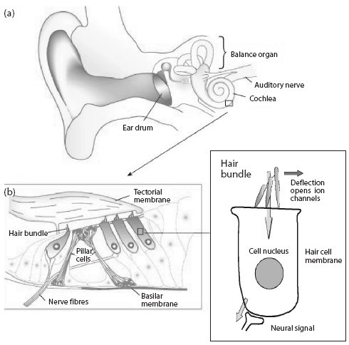
Needless to say, if the hair bundles are damaged or missing there will be no stimulating of the nerve.
Here are some details of the assembly language programming of an embedded Motorola DSP56309 work I did for the MRC-CBU in Cambridge, an overview of cochlear implants, the experiment in question, and the DSP56309 assembly code itself (with notes).
The question was, can a person without normal hearing but with cochlear implants in both ears also detect this phenomena? An experiment was devised to make that determination.
|
|
The lower right rectangle shows a schematic of a single hair cell with its hair bundle. When the hair bundle moves it stimulates the nerve to fire which sends signals along the auditory nerve to the cortex of the brain. The lower left rectangle shows how these are grouped, and the upper diagram shows how they are placed spatially along the cochlea in the inner ear. The mechanics of the cochlea are analogous to a spectrum analyzer in that different bands of the audio spectrum are detected at different places along its length. Lower frequencies near the apex and higher frequencies closer to the base.
Needless to say, if the hair bundles are damaged or missing there will be no stimulating of the nerve. |
|
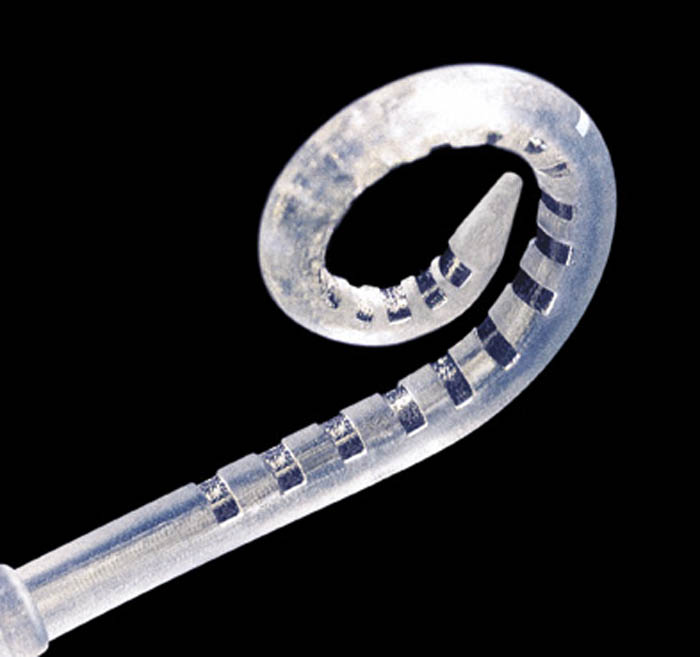
If the hair bundles are damaged or missing but the nerves remain functional, it is possible to place an electrode array in the cochlea and stimulate the nerves directly via electric pulses.
Here is a close up of one such implant with 22 electrodes. To give a size perspective, the mean length of human cochlea is 33 to 36 mm, the spacing between electrodes is about 2.5 mm, and the implant is inserted to a depth of about 25 mm corresponding to a range of 400 to 6000Hz. Because people are different, there is no sense of "precision" placement of the electrode array. Post-operation calibration for the specific patient is necessary. |
|
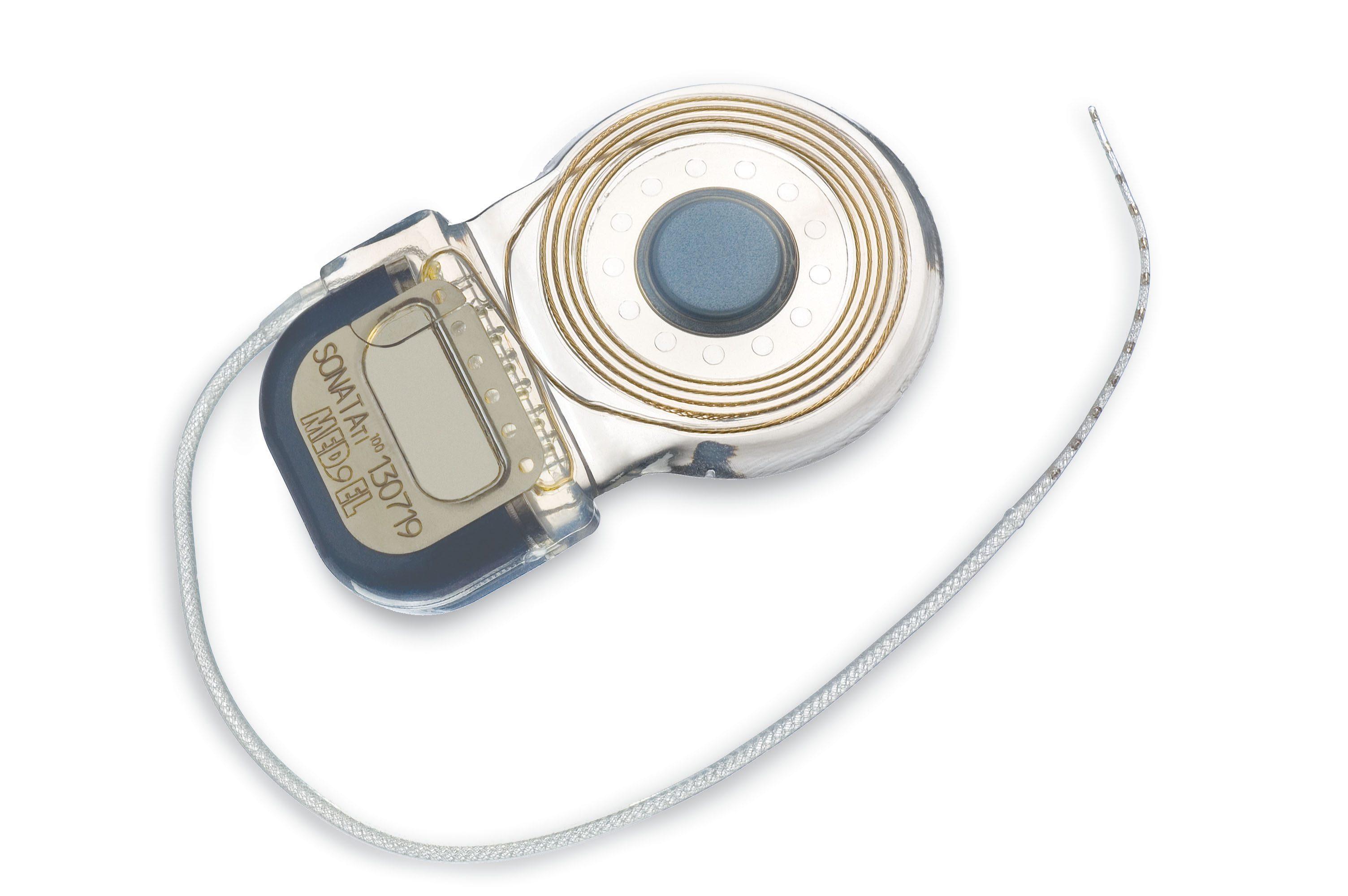
The cochlea implant electrode array is surgically implanted along with a driver, which is an RF receiver coil with passive circuitry to demodulate the RF signal and stimulate the appropriate electrode(s).
Here is a photo of a complete implant. |
|
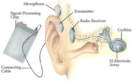
This diagram brings it all together. The speech processor encodes sound from the microphone into impulses for each electrode. These signals are transmitted on an RF carrier to the implant.
It is important to note that the encoding is not a straightforward remapping of the audio spectrum. The perception of sound from the electrodes depends on the intensity, the duration of the stimulus, the pulse repetition rate, and which electrode is stimulated. |
|
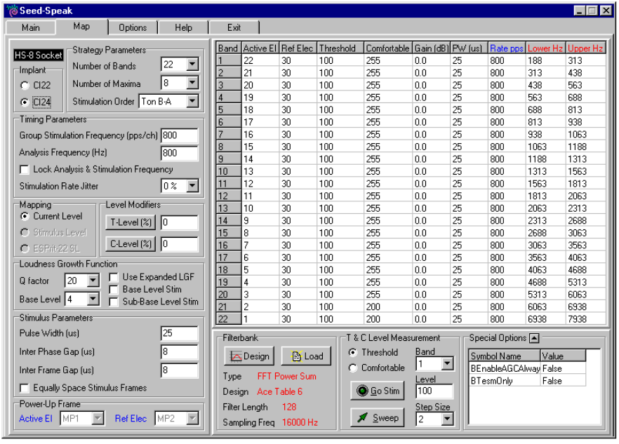
One of the commercial speech processing units available was the SPEAR3 Speech Processor, for which one could obtain a development kit. It was with one of these that the experiment was implemented.
The screenshot to the left is from Womera, the software used in the development kit. This permits connection from the host PC to the SPEAR3 unit via a serial link. |
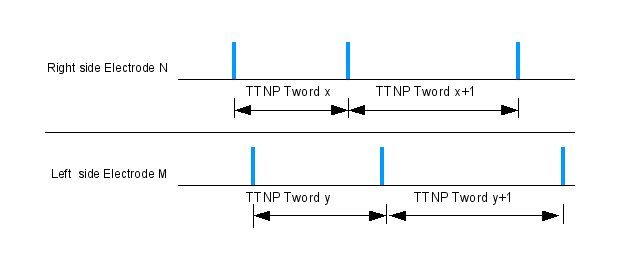
| This is a simplified diagram of the stimuli itself showing that there are two sides, right and left, one of the 22 electrodes per implant, and with the timing of the stimuli determined by a Time Till Next Pulse (TTNP). |
For this experimental setup, the SPEAR3 speech processor would be used in conjunction with patients with Cochlear Corp CI24M implants, Stoph would write a new host PC interface (similar to Womera), and I would write the firmware for the SPEAR3 speech processor. For the first trials the experimenter would select (via the GUI) the desired stimulus and the subject would report what they perceived. Beneath that simple operation was the encoding of the selected stimuli, transmission to the SPEAR3 unit, the decoding then re-encoding of the stimulus, and the retransmission to the implants.
And with all that as background I can commence to detail my part of the project.
Essentially, the aim is to send controlled stimuli to each implant. The critical factors are precise and fixed timing between the two ears. In other words, timing jitter between the two ears will confound the results. Control of amplitude is easy and for this experiment is less an issue. With Windows and a serial link between them, no real-time interaction between the PC and SPEAR3 unit would be possible: the entire stimuli for a single test burst must be packaged and downloaded to the SPEAR3. Straight from the comments in the code, the objectives are:
Whatever else, maximize precision of all timing aspects of the output stimulus
Minimize the delay between High Level Software to output stimulus
Of course there is a primary and overriding objective also: avoiding unwanted and extraneous stimuli. Not only will unpredicted stimulus corrupt the experiment, but sudden strong activation of an electrode is experienced as pain by the subject. The code was reviewed many times to ensure that the stimulus desired by the experimenter was wholly under their control and that no artefacts were present.
Attempts to reach the first objective centered around using the DSP56300's Fast Interrupt Mode. I'll quote from my code comments:
; Perhaps the most important thing to note for anyone wishing to edit this code
; is that in an effort to reduce the unpredictabiity associated with responding to
; interrupts, the Fast Interrput Mode has been used. An unfortunate consequence
; of this is that, given the existing hardware and the limits of instruction
; word size to use this mode, there is essentially only a single instruction that
; will accomplish the task. The reason for this is that two things must occur on
; that instruction, namely 1) Start the encoder to transmit, thus reducing the
; time and indeterminacy from interrupt to pulse output, and 2) making a note
; that this interrupt occured. In the code, that is:
;
;       move    b,x0            a,y:ENCSTRT24R  ; Start Encoder and
;                                               ; note that this interrupt happened.
;
; Most of the apparently peculiar coding is here merely to support that single
; instruction. Things like using the entirety of r4, x0, and y0 as flags so as
; to avoid condition code changes on interrput response. I have noted all these
; things in the code where I could.
;
; Another peculiarity is the inclusion of the entire encoder tables within
; the Y memory space. This was done because writing to the P memory space causes
; the device to reset, a behaviour mediated by the serial interface download code.
; This reset is unacceptable if one wishes to modify the electrode parameters during
; an experiment.
A fast interrupt:
Attempts to reach the second objective amount to minimizing the volume of data to be transfered to the SPEAR3 device to get it to output new stimulus. This resulted in implementing a "compression" scheme for the data which would be preloaded. This moved many burdens to the High Level Software, which became responsible for everything where memory and time constraints were not an issue. This gave rise to the name "SPRTBL", derived from SPEAR3 TaBLe, and is intended to reflect the particular table driven method applied to solve the problem.
The "compression" scheme for SPRTBL is described below and relates to the diagram "The stimuli" above:
; $00002C            $14C81E           Eword 0               |elect #A|  AMP    |elec #R |
; $00002D            $011000           Tword 0               |TTNP (Time Till Next Pulse)|
;                Which is decoded as:
;                The active electrode will be 14 hex, or 20 decimal,
;                The amplitude of the active electrode will be C8 hex, or 200 decimal,
;                The reference electrode will be 1E hex, or 30 decimal, and
;                The time this pulse will be output is 011000  hex, or 69632
The time reference is:
; The values in the counters are related to time by the
; CLK half frequency which drives the timers. The CLK is
; 14.7MHz, so CLK/2 is 7.35MHz, or 0.13605 usec period.
With the memory available on the DSP56309, these tables effectively allow 1/2 of each 16K table (per side) of 24-bit 0.13605 usec time values. With 1000 pulses per second, the table allows 16 seconds of stimulus. This is longer than needed for any particular test burst.
It would be tedious beyond comprehension to elaborate much more on this since that story is already told in the code and comments, which you can read in the next section.
...
						;i;
...
; setup for the X/right side following RELOAD.	;iR;
...
dont_even_startY				;iL;
...
Nearly 100,000 deaf patients worldwide have had their hearing restored by a cochlear implant (CI) fitted to one ear. However, although many patients understand speech well in quiet, even the most successful experience difficulty in noisy situations. In contrast, normal-hearing (NH) listeners achieve improved speech understanding in noise by processing the differences between the waveforms reaching the two ears. Here we show that a form of binaural processing can be achieved by patients fitted with an implant in each ear, leading to substantial improvements in signal detection in the presence of competing sounds. The stimulus in each ear consisted of a narrowband noise masker, to which a tonal signal was sometimes added; this mixture was half-wave rectified, lowpass-filtered, and then used to modulate a 1000-pps biphasic pulse train. All four CI users tested showed significantly better signal detection when the signal was presented out of phase at the two ears than when it was in phase. This advantage occurred even though subjects only received information about the slowly varying sound envelope to be presented, contrary to previous reports that waveform fine structure dominates binaural processing. If this advantage generalizes to multichannel situations, it would demonstrate that envelope-based CI speech-processing strategies may allow patients to exploit binaural unmasking in order to improve speech understanding in noise. Furthermore, because the tested patients had been deprived of binaural hearing for eight or more years, our results show that some sensitivity to time-varying interaural cues can persist over extended periods of binaural deprivation.